This is an older version of the receptacle outlet in the first diagram. The slots are different sizes to accept polarized plugs, but it lacks a grounding slot. Wiring an Ungrounde Polarized Outlet. It shows the components of the circuit as simplified shapes, and how to make the connections between the devices. My site is dedicated to helping you get connected.
The following house electrical wiring diagrams will show almost all the kinds of electrical wiring connections that serve the functions you need at a variety of outlet, light, and switch boxes. A wiring diagram is a simplified conventional pictorial representation of an electrical circuit. Most electrical - wiring - diagrams show the layout of the wiring circuitry, but wattage limitations need to be observed or the wires can get too hot. You can run much higher wattages for wall heaters on 240-volt circuits than 120-volt circuits. It is also more economical.
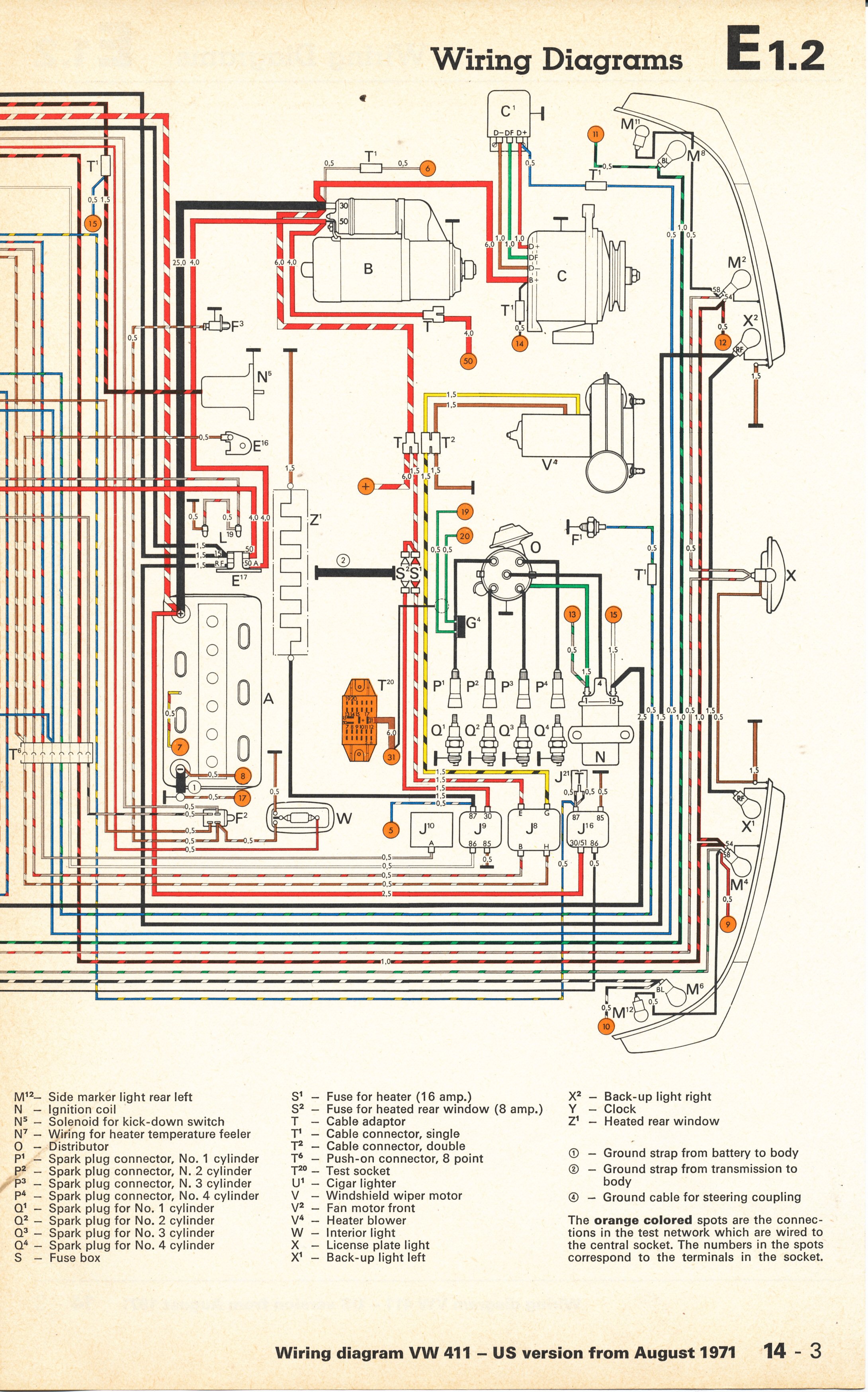
Easy to create wiring plans, schematics, circuit diagrams and more. Normally wiring diagram refers to electrical schematic or circuits diagram. Before we begin please let me tell you what a wiring diagram won’t do. Automotive wire diagrams don’t show the actual position of parts or the physical appearance of the components.
Standard wire schematics don’t reveal the length of conductor wire that runs between the. Electrical symbols and electronic circuit symbols are used for drawing schematic diagram. The symbols represent electrical and electronic components. This app is a complete set of residential and commercial electrical wiring diagrams for two sample houses and for a commercial complex.
Residential and commercial wiring diagrams , also known as. Electrical drawing is a way of illustrating information about power, lighting, and communication for an engineering or architectural project. Our electrical drawing software will assist you in drawing your electrical diagrams using standard electrical symbols minimizing your efforts and making it very simple to use even for beginners. Use this handy trailer wiring diagram for a quick reference for various electrical connections for trailers. Breaker Box– Service Entrance The type of breaker box is the choice of the electrical contractor and the local codes, but most codes state that the electric supply and the breaker box be a 200-Amp service with at least breakers.
Each Diagram that is requested has to be hand selected and sent. They show the diameter of each wire using a label placed at some point along side its drawn line (1) (). This simple diagram below will give you a better understanding of what this circuit is accomplishing. A house wiring diagram is usually provided within a set of design blueprints, and it shows the location of electrical outlets (receptacles, switches, light outlets, appliances), but is usually only a general guide to be used for estimating and quotation purposes.
Wholesale Solar ’s electrical wiring diagrams are CAD (computer-aided design) drawings which show the electrical sequence of all equipment in a system. An electrical diagram is an invaluable resource during the permitting process and system installation. If you are fixing more than one outlet, the wiring can be done in parallel or in series.
Reading wiring diagrams and understanding electrical symbols To understand how to read ladder wiring diagrams , we are going to start with a simple power supply, switch, and light, then we will move on to our control panel sample wiring diagrams that we have used in previous lessons. Being able to use the correct technical terms associated with residential electrical wiring. Understanding how electricity is distributed and controlled throughout your home. Recognizing the different kinds of circuits that may be found in your home.
Reading and creating wiring diagrams and understanding the associated symbols. Now I can choose the car wiring diagrams based on which system I want to work on. You aren’t stuck with the old standards any. Doorbell chimes come in many varieties.

This electrical wiring tutorial video is one of the many electrical circuits explored in DVD of. Electrical wiring diagrams of a PLC panel In an industrial setting a PLC is not simply “plugged into a wall socket”. The electrical design for each machine must include at least the following components. View How To Wire diagrams or consult with our in-office electricians in Mesa AZ free of charge.
Describe and identify the diagram component U. Unlike a schematic, it’s concerned with the connections between the different parts of a circuit or parts of an entire electrical system. Pick the diagram that is most like the scenario you are in and see if you can wire your switch! However, one can do wiring by following the information given in this diagram.

These diagrams are usually intended to illustrate the working of an electric circuit. This article contains a ceiling fan wiring diagram and a light kit. The wiring arrangements for electrical source at the switch and at the ceiling fixture. It could be a single switch wiring or double switch wiring. Every wire connected to a switch are hot wires.
The neutral wires and ground wires are not connected to the switch. The information in this UEWG may contain technical inaccuracies, typographical or diagram errors. Red wire : IG Power Green wire : rpm.
No comments:
Post a Comment
Note: Only a member of this blog may post a comment.