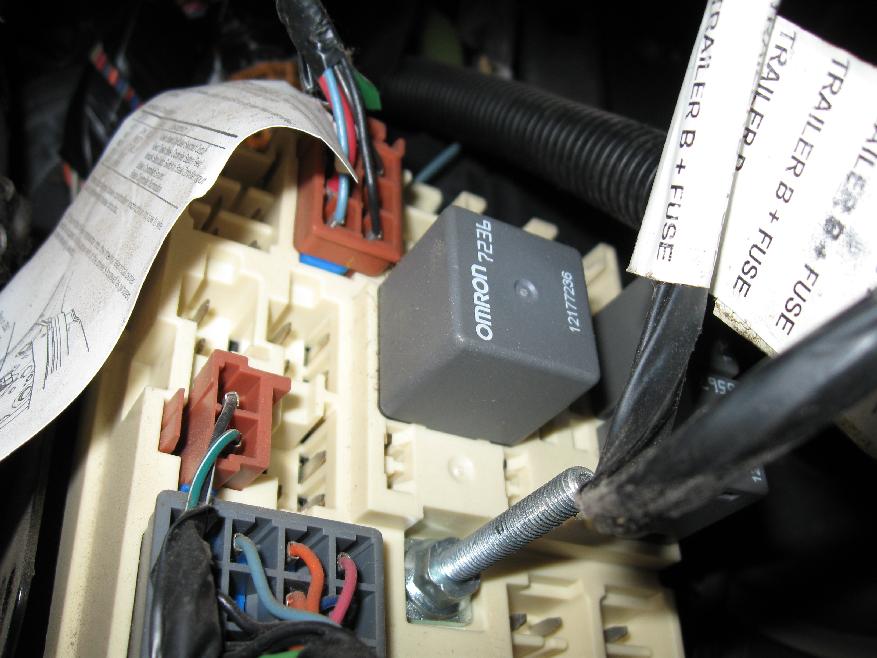
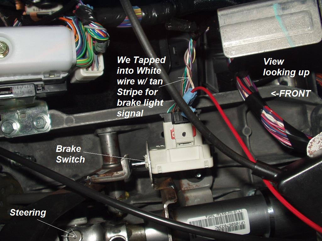
The brake control box should have wires coming out of it. Hopefully you have a wiring diagram for it. Those wires should be: Hot - attached to volts, Ground - attached to groun Output - going to the trailer connector, and Input. Electric brakes work via electro magnets in the brake drums.
There is a brake controlller in the vehicles cab and a wire from the stop light wireing to the controller. TRAILER FEED (Blue wire ) is the wire that allows power for the controller to the 6-way or 7-way trailer connector at the back of the vehicle. If you are lucky (and have the factory tow package already installed) you may already have this wire running from under the dash to the rear of the vehicle.
We then run a jumper wire from the electric brake power wire to the right side brake assemblies (see photo). I have attached an electric brake installation video for you to check out. I go over all the basics on wiring up your vehicle trailer harness and electric brakes. This short video is about trailer brakes , electric brakes and wiring.
It also talks about electric brake controller. The other type of brake system is electronically controlled electric brake control wiring. The trailer brakes are activated electronically by the use of a brake control box mounted under the dash in the tow vehicle. If you plan on towing a trailer that has electric brakes you will need to install a brake control to operate the brakes on the trailer.
For decades, hooking up trailer lights and electric brakes on most cars meant splicing into the wiring harness near the back bumper and just adding the extra load of trailer lights and brakes to the car’s electrical system. ELECTRIC BRAKE SYSTEM COMPONENTS. For these systems to operate properly, the trailer wiring end plug on the trailer must match the wiring pattern of the mating plug on the tow vehicle. The use of an electrical circuit tester is recommended to ensure proper match of vehicle’s wiring to the trailer’s wiring. On the way plugs the 12V wire and electric brake wire may be reversed to accommodate trailer (particularly horse trailers ). Bottom right: white wire , ground wire.
Attach the wire to the axle with zip ties. Various connectors are available from four to seven pins that allow for the transfer of power for the lighting as well as auxiliary functions such as an electric trailer brake controller, backup lights, or a 12V power supply for a winch or interior trailer lights. Trailer Wiring Connectors. I just bought a u-build tandem trailer that needs wiring and a deck.
The axles have electric brake. I was wondering if anyone knows how to attach all wires (pos and neg) to the pin trailer connector. I was assuming you could attach all pos wires to the brake pin and all neg wire to ground. They also have one wire for trailer brakes and one wire for a battery connection.

Note: The black (sometimes red) 12v and blue electric brakes wire may need to be reversed to suit the trailer. Check with a test light or VOM. Uses: horse trailer , travel trailers, landscaping trailer , car trailer , etc.
Unlike surge brakes , electric trailer brakes make an electrical connection to the tow vehicle. This allows for more programmable brake operation and gives the driver the ability to activate the trailer brakes at will, if needed. In order to tow a trailer with electric brakes , the tow vehicle needs to be equipped with a brake control.

A second tail needs to be soldered and spliced into the sensor on the brake pedal. If you have a more complex 4xit may be easier to run a longer cable and tap into a tail-light to get the signal. BLUE CABLE In a standard 7-pin trailer plug the brakes are controlled by the blue wire. The Pby Tekonsha is a proportional braking system with the ability to select between electric over hydraulic or electric trailer brake mode. The other electrical wire is the output cable, which will need to be run between the main control unit and the trailer brakes , or the trailer plug to be more accurate.
Simply run it into the designated pin on the trailer plug and lock it in with the securing screw. Equipment trailers are a vital tool in the construction and landscaping trade. So having them working properly and being well-maintained is a critical part of business success.
The max amperage draw for the brake magnets on a single axle trailer (brakes ) would be 6. Route blue wires along the left and right sides of the trailer frame to the brakes. Complete Breakaway kits, Breakaway switches, in cab controllers, and electrical wiring and plugs are also available. Connect the brake ground wire at each wheel to the trailer frame. Transportation requires that trailers equipped with brakes have a trailer break away system for activation of the trailer brakes , in the event that the trailer should.
This requires a wire from the controller to the trailer brake. This is why some connectors have as many as seven pins, to make provisions for the multiple circuits. Route the black wire along the exterior frame into the engine compartment up to the battery avoiding areas that may pinch or break the wire k. Reconnect the vehicle’s Negative (-) battery cable and install the amp fuse into the fuse holder from step 7. Splice one blue wire of the Break-Away Switch to the electric brake wire coming from the trailer side connector (A - see diagram on next page).

Connect other blue wire of Break-Away Switch to the blue wire (labeled “Brake”) from the Break-Away box ( B ). The Blue wire goes no where near the brake pedal switch. Many styles of electric brake controllers are available that differ in how they look, and the number of brakes they can power, but all of them can be assigned to one of two main groups, Proportional Brake Controllers, or Time Delayed Brake Controllers. Position the floor console forward. If the message center displays TBC FAULT and there are37. Install the floor console front bolts.
Get the Parts You Need Fast.
No comments:
Post a Comment
Note: Only a member of this blog may post a comment.