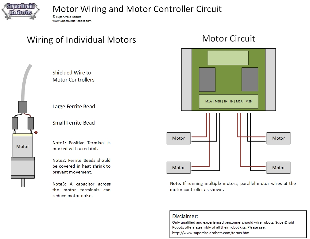
Open the motor cover to access motor terminals. Strip the power wire ends and crimp on terminals. Connect the wiring to the motor terminals. Use wire caps to connect the wires together for the correct rotation.
The trim switch for most boats is fairly simple to wire. The wires are re blue, and green. I think you have confused motor poles with supply wires. Basically the source connection for two pole and four pole motors are the same.
They are hardwired inside the motor during manufacturing and user cannot change the poles. Two power wires (supply) connect with. Yet, with the help of this step by step guide, this task will be become as easy as counting to five. Now, for the purposes of safety, the steps listed below will ONLY demonstrate how to wire a motor for 240V. To avoid confusion obtain a pocket motor wiring guide and refer to it while performing the work.

We mentioned a catch, earlier. With these and other motor wiring variations possible, it’s easy to make a mistake. That drawing we said to follow could be wrong. Before you connect any wires, check the drawing carefully. When diagnosing a faulty automotive motor it is often impossible not to perform major disassembly, such as the fuel pump itself.
Electric Motors General Wiring Instructions. For example, use a red wire nut to connect two 12-gauge wires. On the other en the negative wire goes to the battery and the power wire attaches to a 60-amp breaker. The graphic is a reproduction of a Fasco motor I wired yesterday for a customer. It is basically self-explanatory.
The only thing missing from this graphic is the motor rotation wiring which is a yellow and a purple wire that will reverse the direction of the motor depending on what direction is needed. Star-Delta (Y-Δ) 3-phase Motor Starting Method by Automatic star-delta starter with Timer. How to Wire a Motor Starter. The following is referenced from the Technical and Application Notes section.
If a resistive load is connected to the charged capacitor, the capacitor will discharge at a rate dependent on the resistance of the load. If a resistor, capacitor and a motor are connected properly, the capacitor should be able to run the motor for a short period. Six wire three-phase electric motors are dual voltage motors. The supply voltage is either 2volts alternating current (VAC) or 4VAC. The motor will supply the same amount of power, but with a different load.
Test the motor and battery. Temporarily attach the motor to a battery to make sure everything is operational. If the motor has wires already attache connect the white wire to the positive end of the battery and the black wire to the negative end. If your motor has wires test to see if one of the wires is not connected to the casing of the motor.
If it is, then mark it and then proceed with the same test as with the four wire stepper motor. The two ends that are trailing off the completed coil need to have the enamel sanded off of the Copper Wire (this is extremely important because the more enamel you remove the better electrical connection you are able to make between the AA Battery and the Motor ). The single-phase induction motor can be made to be self-starting in numerous ways. One often-used method is the Split Phase motors. We know about the activity of a capacitor in a pure A. Capacitor-Start Induction-Run Motors. Check the motor connector cover for the proper configuration of 4volt wire connection.

Not all motor manufacturers use the same type of windings. Strip back all motor leads with the wire strippers. A three-phase motor is more efficient than a single-phase motor because of the peculiarities of alternating current (AC). Wire a three-phase motor in either a wye configuration or a delta configuration, in high or low voltage, using a nine-lead set-up.
The Four Wire Stepper Motor. There is not much detailing here. We do not need to bore us with details such as whether this motor is variably reluctance, permanent magnet or hybrid as that only relates to construction. One power wire goes to common.
The 2- Wire Motor 3does not have an internal motor controller. The other goes to the main winding. For 3- Wire Motor Ports (Ports 2-on the Cortex), a Motor Controller must be used in between the Microcontroller and the motor.
No comments:
Post a Comment
Note: Only a member of this blog may post a comment.