This wiring diagram illustrates the connections for a ceiling fan and light with two switches, a speed controller for the fan and a dimmer for the lights. The source is at the switches and the input of each is spliced to the black source wire with a wire nut. Collection of ceiling fan and light wiring diagram. A wiring diagram is a simplified standard photographic representation of an electrical circuit. The white wire is neutral and completes the fan circuit.
The blue wire is the hot wire for the ceiling fan light fixture. The ceiling fan motor does not have a ground wire. The fan control switch usually connects to the black wire and the light kit switch to the red wire of the 3-way cable.
In this diagram , the black wire of the ceiling fan is for the fan, and the blue wire is for the light kit. Ground connection diagram is shown separately. Power Starting at the Switch Box This wiring diagram shows the power starting at the switch box where a splice is made with the hot line which passes the power to both switches, and up to the ceiling fan and light.
Wiring a ceiling fan and light can seem like a daunting task, but it doesn’t have to be. Pro Tool Reviews gives you a visual guide and step by step instructions on making the best connections for your particular ceiling fan installation. ON a scale of 1-1 the level of difficulty on this. Note that ground connections are not shown to avoid cluttering the diagram.
See THIS article for proper ground connections. When installing a ceiling fan, if you are dealing with existing wiring , there are main issues that you must check out before beginning. This diagram is for those who are replacing a light fixture with a ceiling fan.

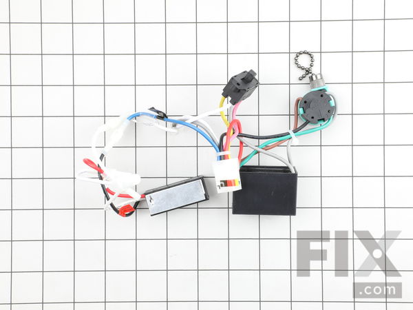
Your existing light fixture was controlled by a switch and only one switch. Unit has three speed fan switch. A small black box with four leads. Need internal wiring diagram.
SMC) Black speed switch, three wire capacitor. You can cop both leads with wire nuts if not using these ends. Most new ceiling fans can be wired to either a single switch or a double switch.

With single-switch wiring , power to the fan is controlled by a standard single-pole wall switch, like a regular light switch. As with any electrical wiring , make sure all wire connections are made securely with the proper size wire nuts, that they are not loose and that no copper strands are showing. The standard Hampton Bay ceiling fan without a remote control has a straightforward wiring diagram. The black wire on the fan is the fan -supply wire , and the blue wire is the light -supply line.
The black and blue wires on the fan are twisted together with the black wire from the house wiring. The wiring color guide does have a lot of useful information in terms of installing and wiring your own Hunter ceiling fan. Pick the diagram that is most like the scenario you are in and see if you can wire up your fan ! Ceiling Fan Wiring Instructions by Wire Color.

Wiring diagrams for lights with fans and one switch read the ceiling fan wiring diagram two switches ceiling fan switch wiring electrical 1wiring diagrams for a ceiling fan and light kit do it yourself. The diagrams on this page are for wiring a ceiling fan and light kit often used in a living room or bedroom. Wiring arrangements for an electrical source at the switch and at the ceiling fixture are include as well as controls for fan spee light dimmer and a single-pole switch hardwired to control the light with a pull chain. This page provides downloads of wiring diagrams for the most common methods of installing Fantasia Fans. I am having issues with the wiring.
There are black wires and white wires in the ceiling. On the fixture itself there are black wires and white wires as well as a small ground wire. I try to wire it white to white and black to black.
When I turn the power back on, the light switch is off but the light comes on. One easy fix is to install a ceiling fan remote control. Then remove the light kit.
That’ll expose the wiring in the housing. Next, remove the capacitor. This is a simple illustrated circuit diagram of ceiling fan. To be noted that the wiring diagram is for AC 220V single phase line with single phase ceiling fan motor.
Here a simple SPST switch is used to supply power or not to the fan motor and a Regulator is used to controlling the fan speed. This ceiling fan wiring diagram shows the power starting at the ceiling fan box. A splice is made with the hot line which passes the power down to the switch box, through the switches and back up to the ceiling fan and light.
Replacing a room’s chandelier or ceiling fixture with a ceiling fan that includes its own light fixture is an easy DIY project for anyone comfortable with basic electrical improvements. If the room has no existing fixture, this project is more difficult and entails cutting through the ceiling and installing new wiring and a switch.
No comments:
Post a Comment
Note: Only a member of this blog may post a comment.